Monday, May 7, 2012

FIM...Part Two...

Back to the jetski fishing rig project...OK, so the rig is about finished. One thing I didn't point out before is that I published the model of the cooler/rod holder to Design Review, and used that in the garage to put this together:


So I'm already doing my part to save the planet...anyway, we wound up making a few changes, but this worked out really well. The rig was placed up on feet, so the Yamaha plume would clear the unit without blowing it off the back end:

The rig holds an Igloo 25 quart cooler, and two Berkley adjustable rod holders. The side mounts allow us to rotate this out for trolling if we want to, although I don't know if they'd hold up to a big king mack or tarpon...but we'll find out. The unit will be anchored down to the tow eyes and the rope ring on the back of the seat. The frame was glued and screwed with stainless steel, so corrosion shouldn't be much of an issue.

Next up - electronics...


We settled on the Humminbird 385 DI combo, due to the small size, waterproof, sonar, GPS and downscan imaging - with the transducer mounted in-hull, so it wouldn't be quite as tacky (like we're not already). We added a gel-based 12 volt battery in a small box in the forward storage compartment, with the openings sealed through the wall to protect the electronics.


Mounting was completed by bolting in a RAM Mounted (Humminbird Specific) in the cup holder - since we never use this, due to the fact the water bottle kept flying out at speed...but this baby ain't going anywhere. Easy removal - just unplug, and loosen the mount, and you can tuck it away for travel. Wiring was coil wrapped to protect from movement during a run, and also to keep the leads from sliding down below the steering.

So, does this qualify for creative? Not sure, but a patent and copyright are on the way...

Next up - the real test in Key West, Florida - watch for pics soon!

Later - David B.

Tuesday, May 1, 2012

It's not BIM...it's FIM - Fishing Information Modeling!

Ya'll know I'm a redneck....but at least I have a little sophistication...sort of. As a graduation present for elder boy from NC State, he's getting a trip to Key West to fish for a while. We're definitely getting our geek on - we're taking the Sea Fox, but also taking a 2010 Yamaha FX HO Cruiser Waverunner:

My toy...
Now, the idea was to just chase the boat, and take some cool video and pics of the boys fishing...but then the redneck in me came out...what if I could fish from the jetski, and catch my own trophies. After several minutes of exhausting research, and seeing what other like minded nutcases were doing (re: http://jetskibrian.com ), we embarked on ways to accomplish this.

First up - design a cooler/rod holder rig. Being a Sunday afternoon with no NASCAR, I came up with a little model in Revit MEP 2012, that used the default PVC pipe fittings:

Schematic Design...it don't look exactly like this...
That's where I found a flaw in the default fittings - while the elbow has the hub connection inside of the fitting, the tee's connection is on the face. Subsequently, I have downloaded the latest version of Charlotte Pipe's Revit PVC fittings, for the rest of my users to enjoy (http://www.charlottepipe.com/Default.aspx?Page=RevitGroups gets you complete libraries - very quickly).

The error in the fittings created an error in my pipe cut lengths on the schedule I defined, so I had to sort of wing it to get the shape correct. We've purchased Berkley adjustable rod holders (of the clamp on variety - https://www.nssnc.com/shop/product/berkley-baarh45-45-rod-holder?ct=10%2C207&sb=brand from my buddies at Neuse sports Shop in Kinston, NC) to attach to the sides of the rig, so I should be able to pull two rods and a net with no issues.

Next up is the installation of a Humminbird 385CI Combo GPS/Fishing finder with Downscan Imaging - this one should be interesting, we're using a RAM mount in the cup holder next to the dash (never could figure out why that was there - the bottles never stay there at 70mph).

So we're in assembly mode - when I get all this put together, I'll add another post with pics for you to enjoy...

Who says BIM geeks never get out...!

Later - David B.

Wednesday, April 25, 2012

Old Guard is becoming New Guard - App for Sweets!

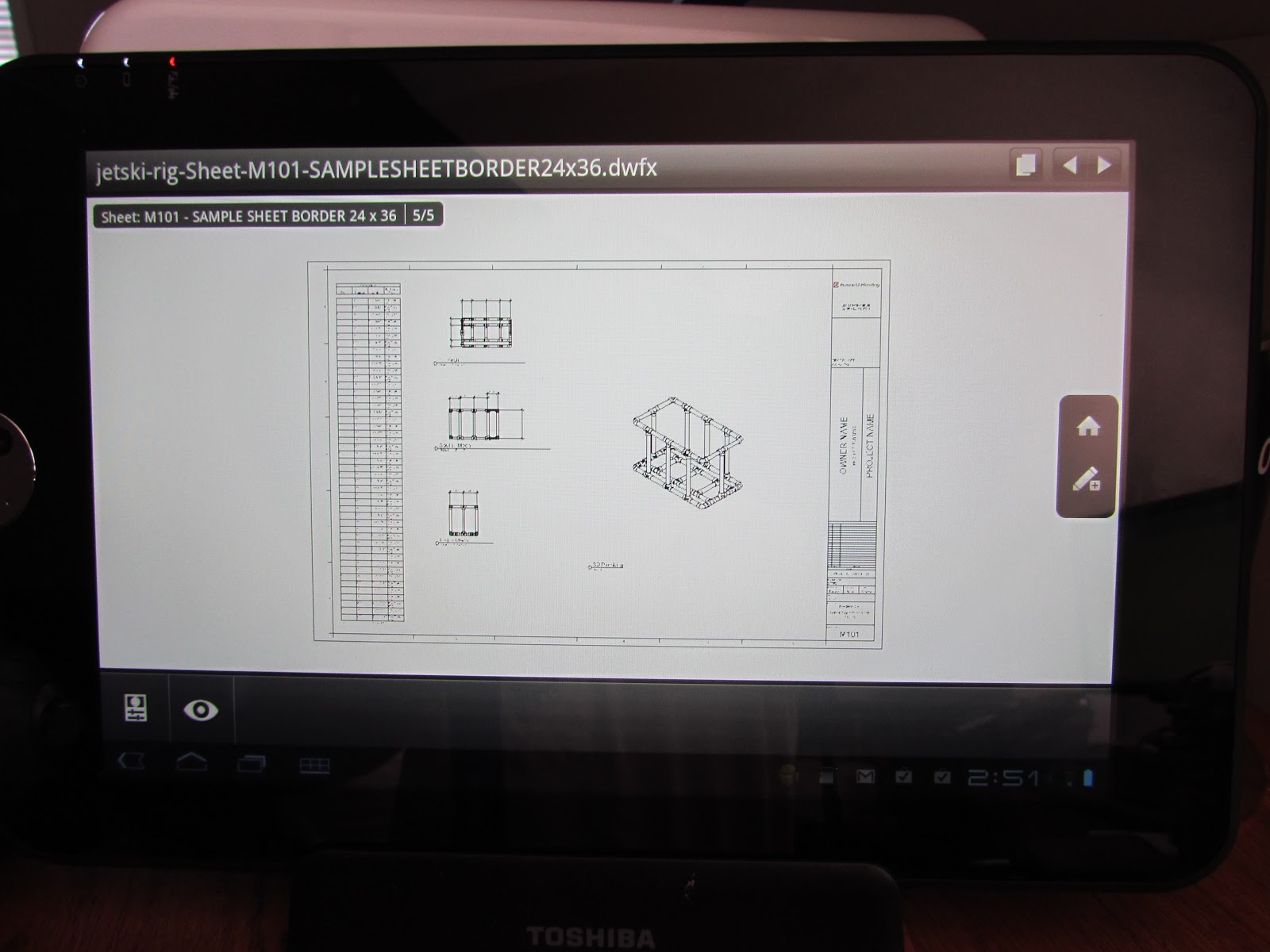
No, we're not talking about candy. McGraw Hill, the publisher of the massive Sweets product specs catalog, has created an app for mobile devices - so you can browse through their catalogs - for free - on your iPhone, iPad, or Android tablet. I downloaded it to my Toshiba Android, and it's slick - just browse, and look under the latest version of CSI spec classifications.

Man, I used to keep a whole shelf of these things, but had to hire somebody with a dually to recycle those things. My tablet's a whole lot lighter...check it out at http://construction.com/sweets/apps/.

Thanks, McGraw Hill!

later - David B.

Monday, April 23, 2012

AutoCAD MEP 2013 - Back with More...

I've had some pets that for whatever reason, just manage to keep hanging around, no matter what I feed them. We had a cat (which I never liked but for whatever reason, loved me) that lasted 22 years, and no matter how grouchy she was, you had to love her.

AutoCAD MEP is getting like that - it's the old comfortable show, that you just can't seem to get rid of. Autodesk is kind of funny about this - they're all into the flash of Revit, and the analytical applications like Vasari and Stimulus that they're so stoked about. But for what it's worth, more than half of Autodesk's sales are still about AutoCAD...and there's a lot of users that are comfortable with it.

So Autodesk re-soled this shoe and put in some new laces, and we're ready to run again. Here's my favorite new stuff:

- Annotation Symbol planes for Front and Left views - this may seem like a small thing, but getting the corrected schematic symbol to appear in section view as the one in top views is actually, uh, important. It's crazy, but AutoCAD MEP has this, while Revit MEP doesn't (in fact, if you rotate a valve in Revit MEP, the annotation symbol gets turned on its edge and you can't see it at all). So I can see the valve consistently in all views. I created an exercise for the CADLearning series that shows this in great detail but you can either draw the linework, or import a design block you've used for years. Either way, this is a great tool.

- MEP Connectors - these data tools snap to the end of a pipe, and then let you make a connection to a Civil 3D or Plant 3D pipe - and pick up the size, material and system. One more step to integration (again, this doesn't work with Revit MEP...but I'm hopin'...).

- Schedule table groups make sorting the data a lot simpler - and gives you the ability to make your schedule's appearance really pop. I had always liked Revit's ability to group items, but this adds more for the ACAD MEP user - you can override the format by group, do group subtotals (and override their format),change orientation by group, indent...it just makes it all smoother.

- Autodesk systems and parts have really be dependent on Layer Keys for years, all the way back to the Softdesk days...but some users just like having their layers in their drawing when they start. Now that you can the layer directly instead of the key, it makes the customization a little simpler.

- The global replace fittings tool is nice - you don't have to pick items like elbows and tees, and worry about the connection getting broken. Being able to change them from elbows to tees (and back again) is even faster than the grip editing tool.

- With Duct Fittings, the radius is now controlled by the inner arc on reducing fittings - so now it looks and models more accurately than in the past.

- The Inclusion of the Fusion - man, I love this tool, for one simple feature. Use it to open an SAT, STL, IPT, etc. file - then use Save As to create a 3D DWG - and now it doesn't matter what the equipment manufacturer used to create their part. By getting the exact part used into the model, it makes the whole lifecycle part of BIM practical. And it comes with all of the BIM packages - both AutoCAD MEP and Revit MEP this year...man, I can't say thank you enough for making this easier. Sure, big files are still a problem, but we all have Windows 7, 64-bit OS, and lots of RAM....right?

You know, there are some days that I wish I was still running AutoCAD MEP all the time...and the 2013 release is making me jealous....but I do have an updated template available - you can get it around AU later this year...

later - David B.


Revit MEP 2013 - New Stuff, My Spin...

Last year, I was working to be the first one out of the gate...but this year, I decided to sit back and watch the free-for-all...I've got a lot of burning questions, now that we have a pretty good bunch of projects running in Revit MEP 2012 - which was a huge improvement over 2011, but still had some holes.

For the packages, I'm running Ultimate, so I'm really up for the infrastructure modeling - can't wait to see what this is going to offer for our site based work. Hope I'm not dreaming too much about this one. Otherwise, I like having one package, where all I need to do is turn on and off the panels I need...nice...

First MEP feature - Autodesk rearranged some of the settings for duct and pipe preferences, moving them from the MEP settings menu to the new routing preferences tool in piping types (aka: AutoCAD MEP routing preferences). I don't mind the move, so the sizes and segment settings are actually part of the pipe tool. The segments, while a nice add, aren't something we'll use much of due to the nature of water and wastewater projects, but for HVAC systems that combine both threaded and flanged systems (for example), this is a good tool to have. You can also still edit the segments under the MEP settings tool.

A good note is that centerlines are now available on connecting geometry such as pipe and duct - this answers a request we've been getting - minor, but needed.

It's the little things that count - now, the double click on the wheel of the mouse gets you a Zoom to fit - about time!

If you're using Revit MEP to size duct, you're going to be happier. This is lot easier now that the version 5 of the ASHRAE Duct Fitting database is part of the program. The user has to still pick the table in some cases (especially if a project from an older release is opened in 2013), but at least the analysis can be completed with better results.

Speaking of duct sizing, you can do a lot more with pressure calcs. Autodesk worked in two areas - calculating flow and pressure separately based on subsegments, and fixing the ability to calculate sizes when taps are used instead of tees. You can also produce a pressure loss report for a piping system, and pass it on to your engineers - make sure your system is well formed and connected, since you can get incorrect results if items just "look" connected.

I'm also real curious how the materials are going to play out. Dan Stine has written a great piece explaining the materials, ( http://www.aecbytes.com/tipsandtricks/2012/issue61-revit.html ) but the part I'm really interested in is the thermal properties of materials - how well will this translate into the heating and cooling load analysis, etc., especially since we're still using Trace (I'm not sure how well any of the older applications will support the import of the material settings - but is it going to work with Vasari?) Will a ductile iron metal material include the right properties, so any heat gain/loss from items that are in direct sunlight be taken into account for the heat load of a room? I'm not sure yet what the impact will be, but at least I'm interested...

Parts and Assemblies were new in 2012, but we haven't touched them...yet. My thought here is to look at how our equipment families go together - should the saddles for a tank be included in the family, but listed as a separate part - so it can be isolated for construction sequencing? Heck, I'm still having a hard time getting all the staff to do the modeling right. Most are on board, but do we really want our engineers breaking it down for the contractor? Are we getting paid enough money to add this feature? I think this will be driven more by the owner for MEP items than for architecture...

Key platform items I'm happy about (for more detail, check out David Light's column - http://autodesk-revit.blogspot.com.au/2012/03/what-new-in-autodesk-revit-2013.html):

- View templates now can update views where the view template was applied, when the view template is changed;
- Being able to apply a view template when you create a view;
- Editing requests are now answer with a direct click - that's a real time saver, makes it easier to not have to step out of what you're doing to grant or deny a request;
- Diameter dimensions - 'nuff said...

So for the MEP user, putting everything into one platform will be of some help. Platform improvements are always good. We're still in the stage of getting the users on the same plane of modeling, and getting them at least to the point of defining systems correctly this year. Upgrading won't be a major headache (except in regard to the segments feature), so that's a plus...but overall, this release is about setting the stage for better analysis of your model. There are still some items that need to be addressed, but getting more out of the model is critical for future users, so we're off to a good start.

Next up - AutoCAD MEP 2013 review...the old man's still got it...

later - David B.
Back from a short Hiatus...

Been extraordinarily busy the past several weeks. First news - the AutoCAD MEP 2013 CADLearning series (www.cadlearning.com) is in the can, and the guys at 4D Technologies are editing and cleaning it up as we speak. Look for some new and updated lessons this year. My favorite new feature in ACAD MEP 2013 is the ability to add schematic annotation symbols to front and left views of parts (specifly valves), so you can actually see the schematic symbol when you cut a section or view from a section. Now, if we can just get this behavior in Revit MEP (hint, hint...).

Next up - Design Review 2013 - looking at about 30 new lessons to help out all those engineers, architects and designers that we don't want touching our BIM models or documents...

thanks! David B.

Tuesday, March 6, 2012

Revit Walls/Structural Walls/Rooms and Spaces...from the MEP Perspective

Now that we're getting deeper into Revit on our projects, we find ourselves in an interesting situation. The question is, who owns the walls? And why does it matter to the MEP user?

Our structure is pretty simple - we break projects up into 3 categories - architectural, structural and MEP/Process (yes, on most smaller jobs, these two are in the same project - the benefits far outweigh the file size issues up to about 150mb). Water projects are a little different than typical building jobs - the process drives the building, instead of the other way around.

Initially we started by saying, the architect owns the non-structural wall, and the structural engineer owns the structural walls. We did our first project this way (and we also let them own their own levels). This didn't work out too well for a couple of reasons. Not keeping the levels all in the architectural model (as architectural levels) cause MEP views to work incorrectly, when copy/monitored into a project. One of the impacts was on the space creation - it didn't like how the structural wall was defined, and caused a variety of areas. Both architectural and structural had levels at the same elevation as well, and this cause a lot of headaches on the MEP side.

Another issue came up when the architect created part of the wall for a room as architectural walls, and the structural engineer made the rest. Even with the structural model linked in and set to be room bounding, a couple of rooms never recognized the structural wall as a valid boundary, if the items are not at the same level or following the same bounding surface area. For example - if a structural user alters a structural wall, to move it to a different level or change the top/bottom constraint, the room and space fail. If the structural wall starts on a different elevation than the architectural wall (regardless of how it's defined, top to bottom or bottom to top), then the room and space may fail.

So here's a couple of ways to look at it. If an area of a building is meant to be occupied - whether it's by people, process fluids or equipment, etc. - then the walls that define the closed boundary should be defined as architectural. This way, regardless of whether they really are structural or not, a room can be properly defined for the area. The space association with room is the driving factor here - in order for a space to correctly track area electrical, HVAC and other power loads, it's got to have a good closed boundary. If the room works, the space will work too. You can always change the properties of the wall in the architectural model to be structural and load bearing, if that's the intent. Once the primary walls are defined, the structural model can copy monitor the walls, and edit the copies as needed to perform their structural layout and analysis.

Anything that's not enclosing an occupied area can be either a structural wall or non-structural, but my preference is that it be defined in the structural model - my thinking is that this applies to foundation walls, footings, etc. that are strictly there for support.

You can always link in structural models, set them to be room bounding, and place rooms where a combination of both structural and non-structural exist - just be aware that changes to constraining levels may cause you to have to rebuild the rooms, and subsequently, the spaces, in your project.

Hope this makes sense - let me know how you're doing it in your projects.

Thanks - David B.